Statement of problem: An optimal marginal and
internal fit plays an important role in the longevity
of a restoration. Increased marginal gaps can cause
bacterial and biofilm adherence. Also, poor internal
fit can lead to decreased retention and resistance
form. There are various techniques available for
the fabrication of restorations. All these techniques
have their own pros and cons. In regards to these
problems, the present study was conducted to find
out whether the manufacturing technique has any
influence on the marginal and internal fit of copings.
Aim: The aim of this study was to evaluate and
compare the internal and marginal fit of Co-Cr
copings fabricated by three different techniques
namely, conventional lost wax technique, 3D resin
printing technique and CAD/CAM milling technique.
Materials and methods: A stainless steel master
model and a custom tray were fabricated. Totally 30
impressions were made and poured with die stone
to obtain 30 die specimens. The specimens were
grouped into three groups. Group 1- conventional
lost wax technique, group 2- 3D resin printing
technique and group 3- CAD/CAM milling technique.
Co-Cr copings were fabricated using the respective
technique. For evaluating the internal fit, weighing
technique was followed. The cross-sectional
technique was followed to assess the marginal fit.
Results: There was statistically significant
difference between the different groups in terms
of internal and marginal fit. The CAD/CAM milling
technique showed better marginal and internal fit
compared to the other two techniques. The 3D resin
printing technique showed better results than the
conventional technique but was not statistically
significant.
Conclusion: Within the limitations of this present
study, the results drawn suggests the use of CAD/
CAM milling technique and the 3D resin printing
technique for fabricating restorations in routine
dental practice.
Key words: marginal fit, internal fit, cobalt-chromium alloy, coping, scanning electron microscope.
Metal ceramic restorations are one of the most
sought out options for fabricating full-coverage
crowns and fixed partial dentures1
. An accurate
marginal and internal fit of cast restorations plays
a vital role in the longevity of the restoration.2
The precision of fit of a restoration is determined
by two criteria: the marginal and the internal
fit. The marginal fit provides a proper seal and an uniform internal fit provides an appropriate
cement space which is necessary for good retention
and resistance of the restoration.3
Holmes et al
defined the internal gap as the measurement
between the axial wall of the prepared tooth and
the internal surface of the casting, while the same
measurement at the margin is called marginal
gap.4
McLean and Fraunhofer in 1971, after clinically
examining 1000 metal ceramic crowns, reported
that marginal discrepancies up to 120µm were
acceptable.5
Initially, gold alloys were considered as the
material of choice for the fabrication of metal
ceramic restorations. But the increased cost of the
gold alloys led to the use of base metal alloys as
an alternative.6
Ni -Cr alloys have been commonly
used for making metal copings. But they also
have their own limitations, due to increased oxide
formation and biocompatibility issues of nickel
and beryllium, they can cause allergic reactions
in many patients. Co-Cr alloys can be considered
as a good alternative to Ni-Cr alloys due to their
better biocompatibility, mechanical properties,
corrosion-resistance and also cost efficiency.7
The conventional technique of fabrication employs
the lost wax technique, which was introduced by
Taggart in 1907. But certain properties of wax like,
distortion, thermal sensitivity and high coefficient
of thermal expansion can make it a less desirable
option.8
Resins can also be used to overcome the
limitations of conventional wax patterns. Resins can offer strength, rigidity, and dimensional
stability if immediate investment is not possible.
But polymerization shrinkage can be an issue with
the use of resins.
The CAD/CAM manufacturing systems have been
introduced for fabricating prosthesis in order to
overcome the disadvantages of the conventional
casting system. It was introduced for dental
applications over 20 years ago to prepare ceramic
inlays and veneers, and several studies have
presented favourable reports.9
It includes both the
additive technique and the subtractive technique.
There are various techniques to evaluate the
marginal and internal fit of restorations. One
among those is the cross-sectional method. In
this method, the prosthesis is cemented onto the
die and then cut. It is then measured for marginal
and internal gap using an optical or electronic
microscope.10 Various other techniques have been
described in the literature. Some of them are the
direct visualization technique under microscope,
replica technique and weighing technique. Also,
clinical evaluation methods using explorer and
scoring, micro-CT and 3D analysis can be used
for evaluation of the restorations.11
Even though different methods are available to
measure the fit of a restoration, there is no clear
consensus regarding the optimal fit. Therefore, the
purpose of this in vitro study was to evaluate the
influence of the different fabrication techniques
on the marginal and internal fit of restorations.
Fabrication of master die:
A stainless-steel die was fabricated using the CNC
(computer numerical control) milling machine (fig
1). This master die was used for the standardized
production of copings. The master die replicated
the form of a prepared premolar tooth. It had a
16-degree total occlusal convergence (TOC), 6mm
height, 5mm diameter and a 360-degree chamfer
finish line.12
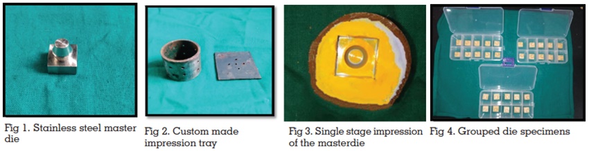
Fabrication of custom-made impression
tray:
For making the impressions of the master die,a
custom-made stainless-steel impression tray
was fabricated (fig 2). The custom tray was in a
hollow cylindrical shape with 2.5cm length and
3cm diameter. One side of the custom tray was
covered with a square shaped stainless-steel
plate. Holes were made on the outer surface of the
cylindrical custom tray and on the stainless-steel
plate. These holes aided in mechanical retention
of the impression material and also provided an
escape way for the excess impression material.
Obtaining the die stone models:
Impressions of the stainless-steel master die were
made with addition silicone impression material
(GC Flexceed, GC India Dental Pvt Ltd, Medak,
India) (fig 3) using single-stage technique. The die was placed on a flat surface and the custom
tray with the loaded material was inverted onto it.
The stainless-steel plate was placed on the upper
side and firm pressure was given from above. A
total of 30 impressions were made. Surfactant was
sprayed into the mold cavity and type IV die stone
was poured using a mechanical vibrator to obtain
the die stone models. The dies were divided into
three groups of 10 dies each (n=10), i.e., Group 1
(Conventional lost wax group), Group 2 (3D resin
printing group) and Group 3 (CAD/CAM milling
group) (fig 4). Impressions made for Group 1 were
poured twice, because the same die cannot be
used for coping fabrication and cementation as
manual spacer application is needed. In case of
the other two groups, cement space is created
virtually, and the same die can be used for coping
fabrication and cementation.
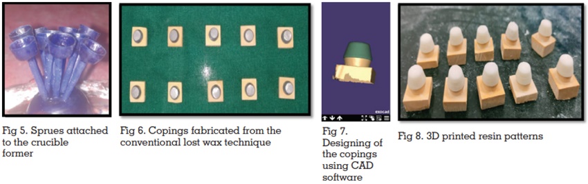
Fabrication of Co-Cr copings with the
conventional lost wax technique:
One layer of die hardener (Yeti dental products,
Germany) was applied on all of the 10 dies.
Later, 2 layers of die spacers(Yeti dental
products, Germany) were applied 0.5mm below
the preparation. Each layer was about 15µm in
thickness, so totally a 30µm thick spacer was
applied. Each die was dipped into a wax pot
containing molten inlay wax to obtain a wax
pattern of 0.5mm uniform thickness, which was
measured using a wax gauge (API wax gauge
caliper, India). The wax patterns were viewed under a magnification glass to assess for any
discrepancy. Prefabricated sprues of 3mm diameter
were attached to all the patterns(fig 5) and they
were invested using phosphate-bonded investment
material (Metavest,Germany) according to the
manufacturer’s instructions. After 30 minutes,
burnout was done followed by casting with Co-Cr
alloy (Wirobond C, Bego, Germany) in an induction
casting machine (Fornax T, Bego). The investment
was then bench cooled and divested. The copings
were then sandblasted, trimmed and finished.
(fig 6)
Fabrication of Co-Cr copings using the
3D resin printing technique:
10 master die stone models were scanned using
an extraoral lab scanner (Medit-T, Medit corp,
South Korea). Designing of the copings was done
using a CAD software (Exocad, GmbH, Germany).
(fig 7) The thickness of the copings was set at
0.5mm and an internal relief of 30µm starting from
0.5mm from the margin was given for the luting cement. The CAD data was sent to the 3Dresin
printing system (Anycubic Photon, China). Printing
of the pattern was done using a UDMA (Urethane
dimethacrylate) based castable resin contained
in a cartridge. After the printing was done, the
resin supports were cut using a carborundum disc.
The resin patterns were placed on the respective
models(fig 8) after which the conventional steps
like sprue attachment, (fig 9) investment, burnout,
casting, divestment and finishing were done,(fig
10) similar to the conventional lost was technique.
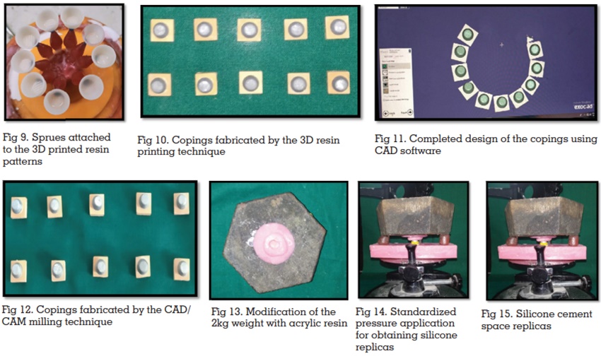
Fabrication of the Co-Cr copings by the CAD/CAM
milling technique:
10 dies were used to fabricate CAD/CAM milled
Co-Cr copings. The dies were scanned by a 3D
laser scanner (Shining 3D DS-EX). The STL data
obtained was transferred to the CAD software
(Exocad, GmbH, Germany) where the designing of
the copings were done. (fig 11) The design included
an internal relief for the luting cement. 30µm of
internal relief was given starting from 0.5mm from the margin. The thickness of the copings was set
at 0.5mm. The data was sent to the CAD/CAM
milling production unit (Dentium rainbow TM Mill,
Dentium, South Korea), where a 5-axis milling of
a solid Co-Cr disc was done. (fig 12)
Making a custom-made set up for
cementing the copings:
To standardize the cementing force, a custom
made set up was used. It consisted of a rectangular
acrylic slab and a 2kg weight. A depression was
created on the surface of the acrylic slab where
the base of the die could fit in. A commercially
available 2kg weight was used to apply pressure
on the copings during cementation. The hole on
the under surface of the 2kg weight was filled with
self- cure acrylic resin and a depression was made
(fig 13) which would fit onto the occlusal surface
of the copings.
Volumetric evaluation of the internal fit:
Equal amounts of addition silicone light body base
and catalyst (GC Flexceed, GC India) were mixed
and loaded onto the intaglio surface of the copings
and the copings were seated on their respective
dies. To apply a cementing force, the custom-made
acrylic slab was placed on the surveying table of a
surveyor, the die along with the coping was placed
on the depression in the acrylic slab. The 2kg
weight was placed on the copings, by positioning
the depression exactly on the occlusal surface. For
additional support, two wax pillars were placed on either side of the acrylic slab. The 2kg weight
was stabilized by lowering the vertical arm of
the surveyor such that it contacted the surface of
the 2kg weight (fig 14). This cementing force was
maintained for 2 minutes until the material set.
The excess material was removed with an explorer
and a No.13 bard parker blade. The coping was
removed from the die with a slight twisting and
rocking motion. Each silicone cement space
replica was retrieved carefully. This procedure
was done for all the 30 copings in total. The silicone
cement space replicas were labelled and kept
separately according to their group. (fig 15) Each
cement space replica was weighed in a digital
analytical weighing machine (Sartorius CP225D).
An increased weight of the silicone cement space
replica indicated a greater cement space and a
subsequent decrease in the internal fit.
Cementing and embedding the
samples:
After making the cement space replicas, the
intaglio surface of each coping was cleaned.
The copings were placed on their respective dies
and inspected for any abrupt marginal gap before
cementation. Type I GIC (GC Fuji, Japan) was
used for cementing the copings. Manufacturer’s
recommendations were followed for mixing the
cement. The same customized set up that was used
for making the silicone cement space replicas was
used for cementing the copings onto the dies. The
excess material was removed using an explorer immediately and carefully. Care was taken not to
damage the margins of the die stone models. The
cementing pressure was maintained for 5mins
until the cement was set. After cementation the
specimens were cleaned and embedded into clear
acrylic resin poured into the putty impression of
a cubic box. (fig 16)
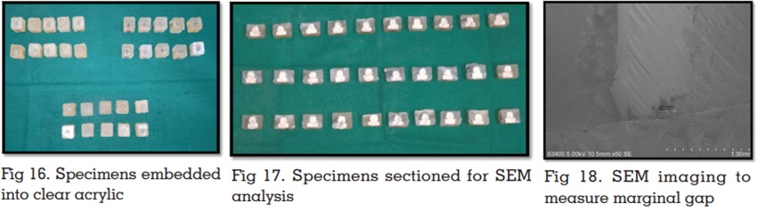
Measurement of the marginal gap using
the scanning electron microscope
After embedding, all the specimens were sectioned
using an electronic saw (fig.17). The sectioned
specimens were used to evaluate the marginal
gap discrepancies. Since, the specimens were
non-conductive, they were sputtered with gold-palladium (Au/Pd) using a sputter coater (Quorum,
SC7620, Quorum Tech, United Kingdom) for 4
minutes to make them conductive and to obtain
a good quality image. Analysis of the specimens
to measure the marginal gap was done using a
scanning electron microscope (Hitachi, S-3400N) at
different magnifications of 50- 200x. The distance
between the external edge of the metal coping
and the margin of the die was used to measure
the marginal gap discrepancy. (fig 18) All the 30
specimens were measured for marginal gap.
Statistical Analysis:
Data obtained were compiled systematically
in Microsoft Excel 2010 spreadsheet. Statistical analyses were performed using a personal
computer in IBM corp. Statistical Package for
Social Sciences software for windows; version
20.0 (Armonk, NY). Both descriptive and inferential
statistics were used. P value of < 0.05 was
considered to be significant. One way ANOVA
with Tukey’s post- hoc test was used to compare
the mean difference between the groups.
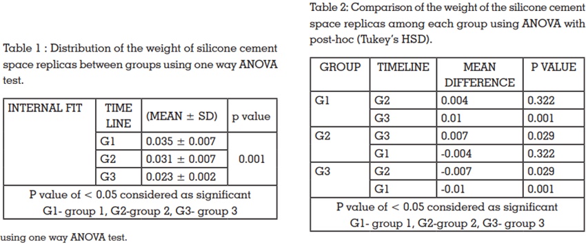
The mean weight of the silicone cement space
replicas for group 1 was 0.035± 0.007 g, for group 2
it was 0.031± 0.007 g and 0.023± 0.002 g for group
3. The mean weights of the silicone cement space
replicas of the three groups were compared using
one-way ANOVA test. A significant difference (P
< 0.05)was seen among the three groups (table
1). The lowest mean weight of the silicone cement
space replicas was seen in group 3, followed by
group 2. Group 1 had the highest values.
Intergroup comparison of the weight of silicone
cement space replicas was made using ANOVA
with post-hoc (Tukey’s HSD). There was no
significant difference when group 1 and group
2 were compared. But there was statistically
significant difference when group 3 was compared
with group 1(P < 0.05)and also with group 2 (table
2)
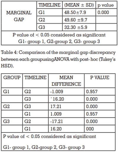
Mean marginal gap forgroup 1 was found to be
48.50 ±7.9µm,49.60 ±9.7 for group 2 and 32.30
±5.9 for group 3. A significant difference (P < 0.05)
was found between the mean marginal gap of the
three groups when they were compared using one-way ANOVA (table 3). Intergroup comparison of the
mean marginal gap between the three groups was
done using ANOVA with post- hoc (Tukey’s HSD).
No significant difference was seen between group
1 and group 2. There was statistically significant
difference (P < 0.05)when group 1 and group 2
were compared with group 3. (table 4)
The chief objective of prosthetic treatment is
to rehabilitate the patient with a well-fitting
restoration. The marginal and internal fit play
an important role in the long-time survival of a restoration.13 The fit of a cast restoration is the most
important factor for it to be clinically acceptable.8,14
For the standardized production of copings, a
custom-made stainless-steel master die was used.
In some previous studies, tooth preparation for
the specimens was done manually which can
lead to incorporation of errors.15,16 Many in vitro
studies have assessed the effect of the margin
configuration on the marginal fit of metal ceramic
restorations. In an in vitro study by Kane et al,
chamfer marginal design for CAD/CAM milled
copings of posterior teeth models showed smaller
marginal gap when compared to the shoulder
margin design6
. Thus, in this study, since a master
model representing a posterior teeth preparation
was used a chamfer margin was opted for the
master model.17
The dimensions of the cement space were also
standardized. Also, alloys containing Nickel have
known to possess more sensitization potential,
thus Co-Cr alloy was used for fabricating the
copings.15,16
The ringless casting technique has shown to
produce copings with improved fit when compared
to metal ring casting. This is because, an equalized
expansion of the refractory mold is achieved by
the ringless casting technique.18 Thus in this study,
the ringless casting technique was followed.
The milling unit that was used in this study to
fabricate CAD/CAM milled copings had a 5-axes
milling function. The increase in the milling axes
facilitates the milling of complex geometries also.3
Vojdani et al have suggested the use of a constant
force of 20N as ideal for cementing the copings8
.
An object of 1kg equals to 9.80665 N of force. In this
study a 2kg weight was used, which corresponds
to 19.6133 N which is closer to 20N. Many studies
in the literature have used finger pressure for
cementing the copings on the dies.7,13,17,19,15,16,20 It
should be noted that though it simulates the clinical
cementation of the copings, since finger pressure
is variable, a standardized pressure cannot be applied on all copings.
Various techniques are available for the
measurement of marginal and internal gaps,
which includes the direct viewing, cross-sectional
technique, silicone replica technique, weighing
the light-body silicone and visual examination.
Nawafleh et al have reported that for measuring
the marginal gaps in CAD/CAM fabricated
restorations, scanning electron microscope
analysis was better than light microscopy.21 Thus,
in this study, the cross-sectional technique with
subsequent scanning electron microscopy analysis
was used to measure the marginal gaps.
The weighing technique used in this study are
similar to that used in the studies by Joo Kim et
al11 and Ucar et al9.
In two separate studies by Al Saady et al22 and
Kocaagaoglu et al23, the marginal fit for CAD/CAM
milled copings was found to be better. The results
of the present study agree with the above studies.
The results of the present study also support the
study by Nesse et al24 in the fact that CAD/CAM
milled copings have better marginal as well as
internal fit.
The results of this study are contrary to the
results obtained by Farjood et al25 in which the
conventional technique was found to be better.
The poor marginal and internal fit of conventionally
cast copings can be attributed to the accumulation
of the manual errors in each step. Also, in the
induction coil heating, due to the increased
temperature some components of the alloy which
have low melting point are lost, making the alloy
more viscous. This can also affect the fit of copings.
According to Bhaskaran et al, vertical marginal
discrepancy of 10-160 µm and internal gap of 81-
136 µm were clinically acceptable. On the other
hand, Moldovan et al13 suggested that marginal
misfit of 100 µm is considered good and 200-300µm is considered as acceptable. McLean and von
Fraunhofer suggested 120 µm of marginal gap as
clinically acceptable27 and the marginal gap of
the copings in this present study were within the
clinically acceptable range. A clear consensus
regarding the marginal and internal fit seems to
be lacking.
It is concluded that the Co-Cr copings fabricated
by the CAD/CAM milling technique had the best
marginal and internal fit, followed by the 3D
resin printed copings and the conventionally cast
copings. Thus, the null hypothesis that there will
not be any statistically significant difference in
the marginal and internal fit among the groups
was rejected. Despite the increased marginal gap
discrepancies in the 3D resin copings and the
conventionally cast copings, the marginal gap
values were within the clinically acceptable range.
Within the limitations of this present study, the
results drawn suggests the use of CAD/CAM milling
technique and the 3D resin printing technique for
fabricating restorations in routine dental practice.
Moreover, future studies with larger sample size
and multiple measuring points are necessary to
further support the adoption of newer techniques
like the CAD/CAM milling and 3D resin printing.