Objective: To provide a new system of spacer
design for the fabrication of complete denture
prosthesis bearing in mind the pattern of residual
alveolar ridge resorption, the stress-bearing, and
relieving areas.
Background: Certain anatomical structures of
the edentulous arches are incapable of bearing
compression and thus, undergo detrimental
changes. Hence, care should be taken to avoid
the application of excessive forces on those
structures. The residual alveolar ridge of maxillary
and mandibular arches have different patterns of
resorption. When areas susceptible to resorption are subjected to unwarranted compression, the rate
of bone resorption accelerates leading to loss of
retention of the prosthesis and diminished support
available for the future prosthesis. Thus, it would
be prudent to design spacers keeping in mind the
resorption pattern of the edentulous arches.
Conclusion: The spacer designs presented in this
article are likely to provide better stress distribution
by displacing the stress-bearing structures and
preventing the resorption of vulnerable areas
by relieving such areas. The new design of the
spacer advocated could limit some amount of bone
resorption, if not, completely prevent it.
Key words: Tissue stops, spacer wax, complete dentures, final impression.
Edentulism is declining at a rate of approximately
1% per year but this is offset by the increasing
life expectancy. Thus, the number of edentulous
patients fairly remains the same or is increasing
slightly.1-2 Rehabilitation with complete denture
prosthesis is a time-tested treatment modality that
serves both the functional and aesthetic needs
of an edentulous patient. They are a great tool
when fabricated accurately, and meticulously
following the proper guidelines. At the same
time, any errors can lead to problems with the
outcome and long-term functionality of the
dentures. Every step in the fabrication of complete
dentures must be given equal attention. One of
the cardinal steps in complete denture fabrication
is impression-making. The objectives behind
making an impression are to provide support,
stability, resistance to dislodgment, aesthetics
for the complete dentures, and to preserve the
underlying anatomical structures.3
The accuracy
of impression-making is paramount in keeping
harmony with the underlying soft and hard tissues
of the denture-bearing area.
Many theories have been put forward by different
schools of thought for recording denture-bearing
tissues. The most significant of them are the
mucocompressive technique described by the
Greene brothers (1900),3-4 mucostatic technique
by Harry L. Page (1944)5
, and the selective
pressure technique by Carl O. Boucher (1951).
According to mucocompressive theory, the entire
denture-bearing area is recorded in function.
The advocates of this technique believed that
the chances of the prosthesis getting dislodged
while carrying out routine functions were very
minimal, but it leads to the placement of additional
pressure on the entire denture-bearing area and
increased chances of residual ridge resorption.
On the other hand, the mucostatic impression
technique deals with making an impression
of displaceable tissue in its passive state, and
interfacial surface tension was considered as one of the main factors that provided retention
for the prosthesis.4
Carl O. Boucher suggested
applying pressure over stress-bearing areas and
relieving the relief areas, creating equilibrium
between the resilient and non-resilient tissues.
Thus, the selective pressure technique is one of the
commonly followed techniques for making final
impressions.6
The selective pressure is provided
by relieving the relief areas using a spacer under
the custom tray.
The custom tray is an individualized impression
tray made from a cast recovered from the
preliminary impressions. A custom tray should
be able to carry the impression material to the
mouth, and control and confine the material to
enable it to record accurately the minute details
of the denture-bearing area.7
Custom trays are
usually fabricated using autopolymerizing acrylic
resins, thermoplastic resins, visible light-cured
resins, or with thermoplastic shellac baseplates.
Space can be created in the custom tray for
providing relief by adapting spacers of different
thicknesses. Various materials employed as spacers
include baseplate wax, casting wax, thermoplastic
sheets, tin foil, etc.8
The most commonly employed
is a baseplate wax used as a spacer under an
autopolymerizing resin custom tray. The objectives
of employing a spacer include providing relief for
the relieving areas and ensuring uniform space for
the final or wash impression material. The main
motive behind providing relief is to ensure that
the areas which cannot withstand forces do not
get compressed in function. When the forces of
mastication continually compress the vulnerable
structures it leads to unwanted changes in the
tissues like resorption of the underlying residual
alveolar bone.
Residual alveolar ridge resorption is a continuous
and progressive process after the extraction of
teeth. The literature suggests different rates and
patterns of ridge resorption for both the maxilla and
the mandible. The pattern of ridge resorption has
to be kept in mind before designing a spacer as the force distribution can be varied and controlled
with the use of a suitable spacer.
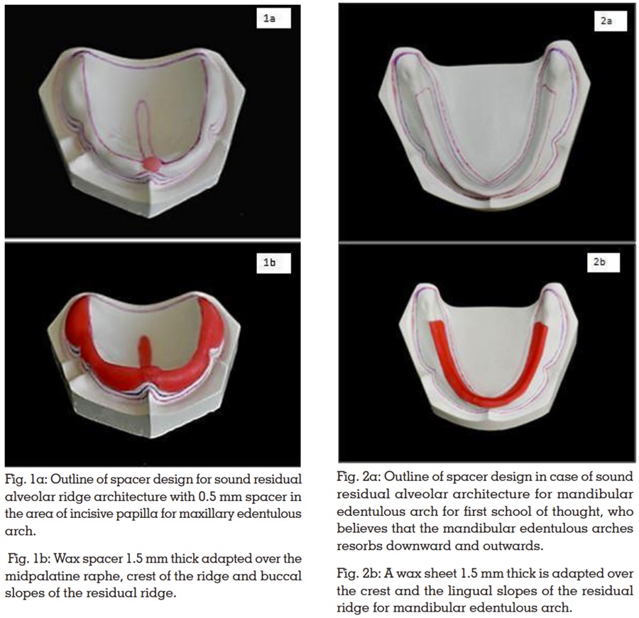
The maxillary edentulous arch: It resorbs upwards
and inwards with progressive narrowing of the
arch due to bone loss that follows the direction and
inclination of the roots of the teeth. The incisive
papilla remains constant as it is little affected by
ridge resorption.9-10
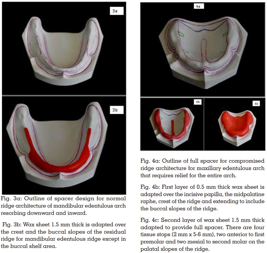
The mandibular arch: There is a bit of controversy
when it comes to the mandibular ridge resorption
pattern. According to one school of thought,
the mandibular ridge resorbs downwards and
forwards. Thus, the alveolar ridge inclines outwards
and the mandible becomes progressively wider.9-10
Whilst, the other school of thought suggests that the
mandibular arch like the maxillary arch resorbs
to shrink downwards and backwards.11-12
The present article aims to present a scientific way
of designing spacers for completely edentulous
arches keeping in mind the pattern of residual
alveolar ridge resorption so that long-term success
can be achieved by preserving the existing alveolar
bone for the conventional complete denture
prosthesis.
Various authors have recommended several ways
and methods for designing spacers and providing
relief during final impression-making. A few
noteworthy of them have been briefly mentioned
here.
1. Spacer design by Boucher CO (1951):6,10
Baseplate wax of approximately 1mm thick for
the outlined border is used to provide relief for the
custom tray that is employed for making the final
impressions. For the maxillary edentulous arch,
the whole of the impression surface is covered
excluding the posterior palatal seal area. The
posterior palatal seal area is excluded to provide
additional stress in this area to achieve a posterior border seal. The author suggests that it also acts
as a guiding stop to help position the impression
tray. In the mandibular arch, wax covers the crest
and slopes of the residual ridge. The borders and
buccal shelf areas on either side are left uncovered,
to apply pressure on the primary stress-bearing
areas. Extra wax can be placed in the region
below the mylohyoid ridge to make space for the
action of the mylohyoid muscle. The author does
not recommend a wax spacer if a metallic oxide
impression paste is selected for making the final
impressions.
2. Concept of relief by Winkler S:13
Selective relief is accomplished for the custom
tray depending on the clinical needs presented
by the particular patient. The usual areas of relief
recommended by the author are the incisive
papilla, the rugae zone, and the midpalatine areas.
A small hole, no more than 1mm in diameter, is
placed in the midpoint of the tray for control of
hydrostatic pressure built up in the tray during the
final wash. He has left the choice of placement of
other escape holes at the discretion of the operator
to control wash impression pressures.
3. Design of spacer by Morrow RM et al.:8
The authors advocate first blocking out the
undercuts, followed by the application of one
layer of baseplate wax over the cast and trimming
it to the previously drawn outline 2mm short of
the resin tray border. Three tissue stops are made
by removing 4mm squares of wax to expose the
cast. The exact location of tissue stops can vary.
The authors think that the size and position of the
tissue stops may vary according to the dentist’s
requirements and sometimes the tissue stops may
or may not be required.
4. Design recommendations by Mac Gregor AR:14
He recommends the placement of a sheet of metal
foil in the region of the incisive papilla and mid-palatine raphe. The author also feels that some
areas that may require relief are maxillary rugae, areas of mucosal damage, and the buccal surface
of prominent tuberosities.
5. Design of spacer by Neill DJ and Narin RI:15
He advocated the placement of a sheet of 0.9mm
casting wax over the outlined area of the cast that
will provide a space between the cast and the
impression tray.
6. Concept of spacer design by Rahn AO and
Heartwell CM:16
Two methods have been advocated by Heartwell-the first method includes providing space and relief
in the prosthesis by scraping off the impression
compound in the area to be relieved. The second
method provides 5 relief holes by placing three
holes along the rugae and two holes in the posterior
glandular region.
7. Spacer design by Sharry JJ:17
The author recommends adapting a layer of base
plate wax over the whole area outlined for the tray
including the posterior palatal seal area. Four
tissue stops, 2mm in width located in the molar
and cuspid region that extends from the palatal
aspect of the ridge to the mucobuccal fold are
given. A relief hole is given in the incisive papilla
region.
8. Design of spacers by Bernard L:18
He advocates placing a layer of 2mm thick
baseplate wax in the area of the casts that usually
have softer tissues as this avoids the displacement
of soft tissues covering the palate and the residual
ridges.
9. Concept of spacer by Halperin G and Rogoff
P:19
They recommended the ‘Philosophy of custom
impression tray with peripheral relief ‘. This is
achieved by placing 1mm of wax on the borders
of the custom tray to provide space for the green
stick compound to form a butt joint with the custom
tray and record the borders accurately.
10. Spacer design by Shetty S et al. (2007):20
According to them, a sheet of 0.4mm thick wax is
adapted over the entire maxillary cast except in
the region of PPS. Over this, a 1.5mm thick layer
of modeling wax is adapted avoiding the crest
of the ridge and the palatal shelves, as the crest
and the palatal shelves are stress-bearing areas.
11. Use of Polyvinyl thermoplastic sheet as
spacer:21
Kaur H et al. (2016) used a polyvinyl sheet that
was vacuum-formed over the cast for providing
space and then the stoppers were provided by
trimming into it. The authors thought that this
method overcomes the variability in the thickness
of the spacer in different regions created while
manipulating the wax.
Maintenance of the orofacial region is essential
and will influence the appearance, function,
communication skills, and interpersonal relations
and has an impact on socialization, thereby
enhancing the quality of life.22 The harmony
of the dentures with the orofacial tissues is of
paramount importance in long-term success.
Hence, maintenance of the existing residual
alveolar ridge is one of the main criteria to be
considered while fabricating a complete denture prosthesis.
To uphold the principles of the selective pressure
impression technique it is very important to provide
proper relief to the reliving structures and at the
same time displace tissues that can withstand
forces without causing any undesirable changes.
There are plenty of spacer designs recommended
in the literature and there are a lot of variations
in the concepts and designs. The earlier designs
have not considered the pattern of ridge resorption
to prescribe the design of the spacer.
The basis for the formulation of the present spacer
design is the pattern of alveolar ridge resorption.
Hence, all the schools of thought related to the
same are incorporated and in turn, it complies
with DeVan’s concept.23 The spacer designs are
delineated based on different ridge conditions
encountered by the clinicians on a day-to-day
basis. The stoppers are placed in such a manner
that it assists the process of impression-making
as well as does not impinge on relief areas. In
addition, relief holes are provided to help the
excess material escape and there is no excess
pressure built up.24
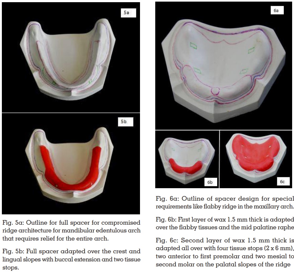
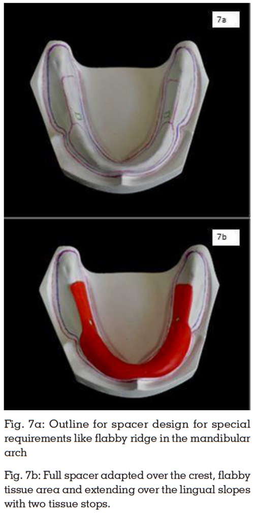
In flabby ridge cases, the most commonly employed
technique is the use of a custom tray with a window
to avoid displacement of the tissue while recording
the same.25 The main concern in cases of flabby
ridges is the provision of enough space, which
is addressed by providing a spacer of 3mm.
The article intends to cover most of the clinically
encountered situations. Any other situation other
than those mentioned can be addressed by
the clinician by applying the same principles
described.
The importance of a good impression cannot be
stressed enough in making a dental prosthesis,
especially in complete denture fabrication where
the entire support and stability are provided by
the underlying tissues. The spacer design helps not just in recording the areas accurately but also
in the preservation of the underlying structures.
A new spacer design is suggested here keeping
in mind the pattern of alveolar ridge resorption.
This novel approach should address the frequently
encountered problems of ridge resorption to some
extent if not completely curb it.