Production stages are now becoming more automated in the field of dentistry. Over the last two decades, computer assisted designing and manufacturing of highly durable and aesthetically satisfying prosthesis become the centre of focus. CAD/CAM generated dental restorations have many advantages that include: the access to almost defect-free, prefabricated and controlled materials; an increase in the reproducibility and quality of the restorations and also data storage that commensurate with a standardized chain of production; it will provide an improvement in planning, increase in efficiency and improvement in precision.
Key words: standard transformation language, subtractive manufacturing, additive manufacturing, digital implant prosthesis, computer navigated surgery.
CAD-CAM is an acronym for COMPUTER
AIDED DESIGNING – COMPUTER AIDED
MANUFACTURING. Use of computer systems to
assists in creation, modification, analysis and
optimization of design. CAD-CAM usage in dentistry began in mid-1980s. CAD-CAM is a
field of dentistry and prosthodontics using CAD-CAM, to improve the design and creation of dental
restorations, especially dental prosthesis, including
crowns, inlays, veneers, onlays, fixed bridges,
dentures and fixed dental implant restorations.
CAD-CAM has become the centre of attention,
because of its potentiality to deliver a highly
durable and aesthetically satisfying restoration
on the same day of patient visit.
All CADAD-CAM system consists of three components.
A scanner or digitalization tool is used to transform object’s geometry into digital data, that can be processed by system.1 Basically there are two different type of scanners available:
In optical scanners white light projections or a
laser beam can serve as a source of illumination.1
the basis of this type of scanner is the collection
of three dimensional structures in a ‘triangulation
procedure’. In this system, the light source and
the unit containing the receptor are arranged in
a definite angle to another. Through this angle
the computer can calculate a three dimensional
data set from the image on the receptor unit2
.
Example: Lava Scan ST (3M ESPE, white light
projection), es1 (etkon, laser beam)
In mechanical scanners, the prepared master cast
is read line-by-line mechanically by means of a
ruby ball and the structure is measured three-dimensionally. The diameter of the ruby ball is
set to the smallest grinder in the milling system,
with the result that all data collected by the system
can also be milled.3,4
Example: Procera scanner from Noble biocare
(fig 1)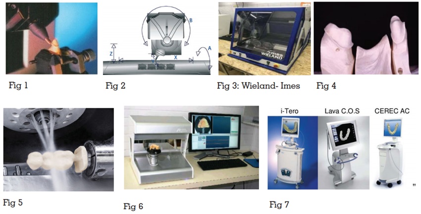
It processes data and, depending on the
application, produces a data set for the product
to be fabricated.2
Example: exocad, CEREC SW 4.5, TRIO software
Suite, Planmeca PlanCAD 6.0
Various data formats are used to store the data
for construction. The basically used format is
standard transformation language (STL) data.
It transforms the construction data set produced with CAD software into the desired product. They are of two types namely
Subtractive manufacturing is a process by which 3D objects are constructed by cutting the materials from a solid block of material. Processing devices are classified based on the number of milling axes (fig 2):
X,Y,Z- 3 spatial directions, A- tension bridge, B
– milling spindle
The 3 axis milling device has degrees of movement
in all the three spatial directions. In this system
the mill path points are defined by X -, Y -, and Z
– values. All 3-axis devices applied in the dental
field can be able to turn the component by 180°
in the course of processing the outside and the
inside. A milling of axis divergences, subsections
and convergences, is not possible. This demands
a virtual blocking in such areas.1
Examples of 3-axis devices: in Lab (Sirona), Cercon
brain (DeguDent), Lava (3M ESPE).
In addition to movement in 3 spatial directions,
these devices also have rotatable tension bridge.
Hence, a large vertical height displacement into
the usual mould dimensions can be done during
bridge constructions and thus save material and
milling time.1
Eg: Zeno (fig 3)
With a 5-axis milling device there is also, in addition to the three spatial dimensions and the rotatable tension bridge (4th axis), the possibility of rotating the milling spindle (5th axis) . This enables the milling of complex geometries with subsections, as for example, lower jaw FPDs on converging abutment teeth (fig 4).1
Dry Processing:
Dry processing is applied mainly with respect
to zirconium oxide blanks with a low degree of
pre-sintering.5
This offers several benefits:
Wet processing:
In wet processing the carbide cutter or milling
diamond is protected by a spray of cool liquid to
prevent overheating of the milled material (fig 5). This kind of processing is necessary for all metals
and glass ceramic material and processing of
zirconium oxide ceramic with a higher degree
of pre-sintering. A higher degree of pre-sintering
will leads to reduction in shrinkage factor that in
turn will enables less sinter distortion.5
Examples:
Zeno 8060 (Wieland-Imes), Everest (KaVo), inLab
(Sirona).
It is known as 3D printing because it describe a
manufacturing approach that builds objects one
layer at a time, adding multiple layer to form an
object. It is also known as rapid prototyping. It can
be used for construction of metal structures either
directly in metals or metal alloys like RPD, FPD,
polymerized prosthesis and silicone prosthesis or
indirectly by lost wax process or printing in burn
out resins.
Three different production concepts are available in dentistry, depending on the location of each component of the system, it includes
All components of the CAD/CAM system are located
in the dental surgery. In this type of production,
the tooth preparation can be scanned intraorally
and by selecting appropriate materials, the dentist
can fabricate the restoration and cement it in a
single appointment.7
Example: CEREC System (fig 6)
In this system the impression or the master cast
will be send to the laboratory. Then the process of
scanning, designing and processing the restoration
will takes place in the laboratory.7
Example: i- Tero, Lava C.O.S, CEREC AC (fig 7)
In this system the data sets produced in the dental laboratory sent to the production centre, where restorations will be produced with a CAD/CAM device in the milling centre and the prosthesis will be sent to the responsible laboratory and to the dentist.7
CAD/CAM devices generally process the following
materials:
Metals:
At present chrome cobalt alloys, titanium, titanium
alloys are processed using CAD-CAM milling
devices.
Examples: Everest Bio T-Blank (KaVo, pure
titanium), coron (etkon: non-precious metal alloy).
Resin materials:
Used for the milling of lost wax frames for
casting technology. Used directly as crown and
FPD frameworks for long term provisional or for
full anatomical long term temporary prosthesis.
Prefabricated semi-individual polymer blanks
(semi-finished) with a dentine enamel layer are
also available (artegralim Crown, Merz Dental).1
Silica based ceramics
Grindable silica based ceramic blocks are used
by CAD/CAM systems for the manufacturing of
veneers, inlays, onlays, partial crowns and full
crowns (anatomically partially reduced, fully
anatomical). Various manufacturers now offer
blanks with multicolored layers [IPS Empress
CAD Multi (Ivoclar Vivadent), Vitablocs TriLuxe
(Vita)], for the production of full anatomical crowns.
Lithium disilicate ceramic blocks are particularly
important and are used for full anatomical anterior
and posterior crowns, for copings in the anterior
and posterior region and for three-unit FPD
frameworks in the anterior region due to their high
mechanical stability of 360 MPa.8,9 Glass ceramics
are particularly well suited to chairside application
as a result of their translucent characteristics, similar to that of natural tooth structure.10
Infiltration ceramics
Infiltration ceramics are processed in porous,
chalky condition as grindable blocks and then
infiltrated with lanthanum glass.
Aluminium Oxide (Al2
O3
)
Aluminium oxide is indicated in the case of crown
copings in the anterior and posterior area, primary
crowns and three-unit anterior FPD frameworks.12
Examples of grindable aluminium oxide blocks:
InCoris Al (Sirona), In-Ceram AL Block (Vita).
Yttrium Stabilised Zirconium Oxide
(ZrO2
, Y-TZP):
Zirconium dioxide is a high-performance oxide
ceramic with high flexural strength and fracture
toughness compared with other dental ceramics
offer the possibility of using this material as
framework material for crowns and FPDs, and,
in appropriate indications, for individual implant
abutments.13
Examples of Zirconium oxide blocks: Cercon
Smart, Lava Frame (3M ESPE), Ceramics.
Digital impression:
It is a positive replica of the oral structures.
For the success of fixed partial dentures like
ceramic restorations internal fitness and
marginal adaptation are important.14 As there
is no dimensional inaccuracy or changes in the
impression or the cast because the impression will
an optical impression and the cast are 3D printed/
milled using polyurethane or styrofoam material.
No need for disinfection of the impression, it is
easy to sore and comfortable for the patients and
it reduces the patient treatment time.
Fixed Prosthesis:
The production of long-term temporary prostheses,
from single unit to full bridge, coping, 3/4th crown,
full crown, veneers is possible, as a result of the
use of a virtual wax up on the computer, become
faster, more convenient and more predictable.1
Removable Prosthesis:
Commercially available CAD/CAM dentures
include
Using CAD/CAM it is possible to deliver the
complete denture in two visits. Less chairside time
needed and is more comfortable for the patient.15
Digital Implant Prosthesis:
Numerous implant planning softwares are
available which aids in accurate placement of
implants.
The two types of computer assisted implant
surgeries includes,
Computer guided surgery:
CAD/CAM designed surgical guide is used for
accurate placement of the implants.16
Computer navigated surgery:
The computer navigated surgery is a direct method,
where the position, angulations and the distance
of implant to the vital structures can be viewed
directly on the screen during implant placement.
It helps in more accurate placement of implants.
CAD/CAM system enables the dentist to provide
highly durable and esthetically satisfying
restorations on the same day of patient visit.
It is more time saving and comfortable for the
patient. The introduction of new systems and the
evolution of current systems demonstrate expanded
capability and improved quality of the prosthesis.