Introduction/Background. Errors can be introduced in
implant placement when using stereolithographically
manufactured fully limiting surgical guides due
to various factors, and at various steps, such as
during designing and manufacturing of surgical
guides (intrinsic error), due to built-in variations in
design of mechanical components of guide systems
and implant dimensions (inherent error) or due to
placement error by the operator (operator error).
Aim. The aim of this study was to evaluate influence
of various factors on implant position when using
these guides.
Materials and Methods. Prosthetically-driven implant
positions were planned with pre-operative cone
beam computed tomography (CBCT) data and
digital scans using a computer aided designing
(CAD) software. Static guided implant surgery
was performed under local anaesthesia using
fully limiting mucosa-supported surgical guide.
Pre-operative and post-operative CBCTs were superimposed using surgical sleeve as a reference
to evaluate the placement error by operator (N=12).
To evaluate intrinsic error, standard tessellation
language (STL) files of the virtual design of the surgical
guides and the STL file obtained after scanning the
3D printed stereolithographic surgical guides were
superimposed. Inherent error was calculated using
a geometric model.
Results. Intrinsic error was observed to be a major
contributing factor in angular deviation of implant,
linear deviation observed at implant shoulder as well
as at implant apex. Operator error was observed
to be a major contributing factor for mean vertical
deviation observed at apex of implant.
Conclusion. This study showed that accuracy of
implant placement was largely influenced by
discrepancies introduced during designing and
manufacturing of stereolithographic surgical guides
as compared to other sources.
Key words: Stereolithographic surgical guides, error, implant placement, static guided surgery
Static guided fully limiting surgical approach for
implant placement enables clinicians to perform
implant surgeries with improved accuracy, ease,
significantly lesser trauma to the tissues and in
shorter time duration.1-6 The precision of such
systems is of paramount importance and minor
discrepancies can result in subsequent surgical
as well as prosthetic complications.7
Errors can be introduced due to discrepancies
in designing, manufacturing of guides, built-in
design variations of mechanical components
of guide systems and implant dimensions or
due to operator related causes.8-22 Thus, the
cause of overall error in final implant position
is multifactorial and would be a cumulation
of errors introduced due to above-mentioned
factors.23-24
Hence, the purpose of this study was to evaluate
the influence of various factors on final implant
placement when using stereolithographic fully
limiting surgical guides. The null hypothesis
was that no error would be introduced in implant
placement due to various factors.
This study was conducted after obtaining pre-requisite approval from the institutional ethical
committee. Informed consent was obtained from
the patients included in this study.
The following variables were defined for the
purpose of this study:
Intrinsic Errors (ItE): Error introduced during
the designing and manufacturing of the
stereolithographic guides.
Inherent Error (IhE): Error introduced as a
result of built-in variations in the design of
mechanical components of fully limiting surgical
guide systems as well as variations in implant
dimensions.
Placement error by Operator (OE): Error
introduced while implant placement as a result
of operator’s skill and experience in different
clinical situations.
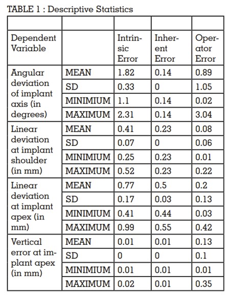
Angular deviation of implant axis: Angle in
degrees between the central axis of the implant
in the digitally planned position and the central
axis of the implant in the final position.
Linear deviation at implant shoulder: The
distance between the central axis of the implant
at the shoulder in the digitally planned position,
and the central axis of implant in the final
position.
Linear deviation at implant apex: The distance
between the central axis of the implant at the
apex in the digitally planned position, and the
central axis of implant in the final position.
Vertical deviation at implant apex: The vertical
distance between the apex of the digitally
planned position of implant and the horizontal
plane from the apex of final position.
The sample size calculation was done based
on the standard deviation values obtained
from a previously conducted study by Geng
et al24 using the formula n=Z2 SD2/d2 where,
n= Desired sample size, Z= Standard normal
deviate (1.96), SD= Standard Deviation, d=
degree of accuracy required (0.02). A minimum
sample size of 5 implants was calculated to get
statistically significant results.
This study included a total of 13 implants placed
using mucosa-supported stereolithographic
fully limiting surgical guides (DIOnavi Digital
Navigation Implant system; DIOnavi). Pre-requisite parameters for inclusion in the study
were adequate bone volume as seen on CBCT,
D2 or D3 quality bone, adequate mouth opening
with a straightforward or advanced Surgical
SAC classification.25 Implant sites requiring bone
augmentation and sinus elevation procedures
were excluded.
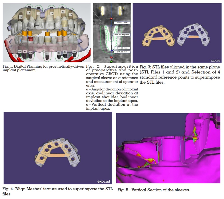
Pre-operative CBCT data and digital scans
of a completely edentulous patient who was
indicated for full mouth implant placement was
obtained. Prosthetically-driven implant positions
were planned using a computer aided designing
(CAD) software (Implant Studio; 3Shape)
(Fig.1). Stereolithographic surgical guides were
subsequently designed and 3D printed (Probe;
DIO Inc) using a commercial printable resin
(DIOnavi-SG; DIO Inc). The implant placed in
maxillary right second premolar region was excluded from the study since indirect sinus
elevation procedure followed by conventional
implant placement was performed in this region.
Static guided implant surgery was performed
under local anaesthesia. The fully limiting
mucosa-supported surgical guides were placed
intraorally and checked for fit. The guide was
secured firmly using fixation screws. The tissue
punch was followed by the bone-flattening drill.
A pilot drill of 2.0-mm-diameter along with the drill key was used to prepare implant site. The
implant osteotomy was then completed using
a series of sequential drills as per the protocol
provided (DIO Navi Guide; DIO Inc). Implants
were then placed with the surgical guide secured
in place (implant dimension: 13 mm X 3.8 mm in 11,13,21; 11.5 mm X 3.8 mm in 31,33,43; 11.5
mm X 4.5 mm in 44; 10 mm X 4 mm in 23; 10
mm X 4.5 mm in 34,36,46; 8.5 mm X 4 mm in
25 regions respectively). A post-operative CBCT
was taken immediately after implant placement
prior to removal of the surgical guide. This
post-operative CBCT data was superimposed
onto the pre-operative virtual implant planning
data using surgical sleeves as a reference to
calculate the error introduced by the operator
while implant placement using a CAD software
(Implant Studio; 3Shape) (Fig. 2).
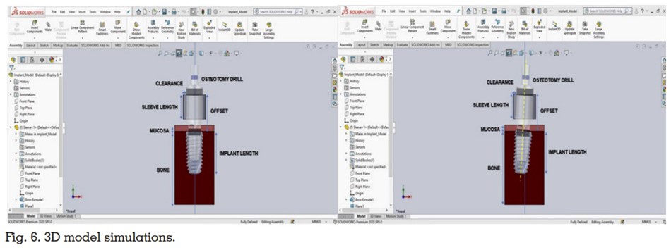
To evaluate ItE, the standard tessellation
language (STL) files of the virtual design of
surgical guides and the STL file obtained after
scanning the 3D printed stereolithographic
surgical guides were superimposed using
a computer-aided design software program
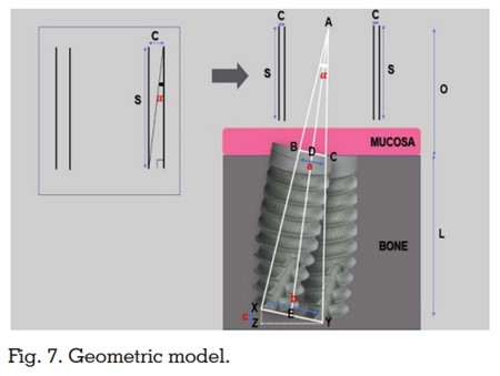
(exocad; exocad GmbH). The Align Meshes
feature was used to superimpose the 2 STL files
using 4 points on the central bar of the surgical
guide as a standard reference (Fig 3-4). The
methodology followed was exactly as previously
explained by Shah et al.7
The “Measurement
Tool” was used to make angular and linear
measurements between the margins of the
sleeves at the point of intersection of the planes
and sleeve margin mesially, distally, buccally,
and lingually by using the Color Map feature as
a guide (Calibrated from 0 to 50 mm with 5-mm intervals) (Fig 5).7
Formulas provided by Shah et
al7 were used to calculate the linear deviation at
the shoulder and apex of the implant as well as
the vertical deviation at the apex of the implant.
To calculate the IhE, this study utilized a CAD
software software (SOLIDWORKS® 2021
Software; SOLIDWORKS) and a geometric
model. A 3D CAD model was designed to assess
and evaluate the errors introduced during
implant placement by varying the design of
mechanical components of the surgical guide
as well as the implant dimensions (Fig. 6). For
designing this 3D CAD model, the standard
tessellation language (STL) files of the metal
sleeve, implant and the final drill of a commonly
used static guided implant system (DIOnavi
Digital Navigation Implant system; DIOnavi)
were obtained via scanning of the respective
components using a dental table-top scanner
(MeditT300; MEDIT).
The static guided surgery was then simulated
using a CAD software (SOLIDWORKS® 2021
Software; SOLIDWORKS). The “assembly” as
well as the “plane and angle orient” feature was
used to assemble and orient the individual STL
files with respect to each other. The dimensions
of the surgical guide as well as the implant were
varied to evaluate their effect on final implant
position. Clearance, offset, sleeve length, and
implant length were identified as the 4 factors which affected the implant position and were
considered further.
Clearance: The difference between the inner
diameter of the metal sleeve and the diameter of
the shaft of the drill.
Offset: The distance between the occlusal
surface of the metal sleeve and the shoulder of
the implant. Offset is sleeve length plus distance
between the sleeve base and implant shoulder.
Sleeve length: Total length of sleeve.
Implant length: The length of the implant from
the shoulder to the apex.
The static guided implant system used in this
study (DIOnavi Digital Navigation Implant
system; DIOnavi) has a clearance of 100 microns,
sleeve length of 4mm, offset values 9 mm, 10.5
mm and 12 mm and implant length of 7 mm, 8.5
mm, 10 mm, 11.5 mm, and 13 mm. A geometric
model was prepared based on the above mentioned contributing factors to obtain formula
for calculating the error that can be introduced
in implant position (Fig. 7). For obtaining the
geometric formula, a perpendicular bisector
was dropped from point A to point E bisecting
such that ∠ADB=∠ADC=AEX=AEY=90
degrees. ABC and AXY are isosceles triangles.
By applying the principles of geometry, following
formulae were derived:
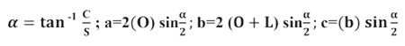
where C=Clearance, S=Sleeve length,
O=Offset, L=Implant length, Angular deviation
of implant axis, a=Linear deviation at implant
shoulder, b=Linear deviation at the implant
apex, c=Vertical deviation at the implant apex.
The data were entered into a spreadsheet
(Excel; Microsoft Corp) and subjected to
statistical analysis (One-Way ANOVA and
Bonferroni-Adjusted Post Hoc Tests for intergroup
comparison) using a statistical software program
(SPSS Statistics v17.0; SPSS Inc).
The mean, standard deviation, minimum and
maximum values for angular deviation, linear
deviation at shoulder and apex of implant and
vertical error observed at the apex of the implant
have been shown in angular deviation values
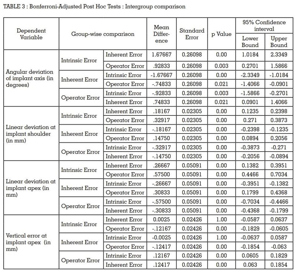
are shown in Table 1. The results for One-Way
ANOVA and Bonferroni-Adjusted Post Hoc Tests
for intergroup comparison have been shown in
table 2 and 3 respectively.
ItE was observed to be a major contributing
factor to the angular deviation of the implant
followed by OE. IhE contributed the least to
angular deviation (P value <0.05).
The major contributing factor for linear deviation
at shoulder of implant was found to be ItE followed by IhE. The effect of OE was found to be
the least at the shoulder of the implant (P value
<0.05).
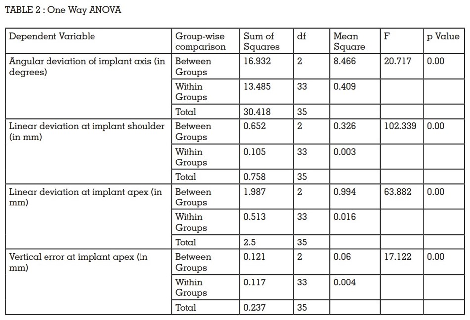
Greater linear deviation was observed at the
apex as compared to the shoulder of the implant.
The major contributing factor for linear deviation
at apex of implant was found to be ItE followed
by IhE and OE (P value <0.05).
The major contributing factor for vertical error
observed at the apex of the implant was found
to be error introduced by the operator during
implant placement. The impact of ItE and IhE on
the vertical deviation of the implant at the apex
was found to be negligent (P value <0.05).
Further, no correlation could be established
between the location of implant (maxillary or mandibular arch and anterior or posterior
region) and proximity of implant to the fixation
screws with the various types of errors.
The current study calculated the influence
of various factors (ItE, IhE and OE) on
the final implant placement when using
stereolithographically manufactured fully limiting surgical guides. Based on the findings
of this study, the null hypothesis that no error
would be introduced in implant placement due
to ItE, IhE and OE, was rejected.
Intrinsic error can be introduced by variety of
factors such as errors introduced during data
acquisition, software handling, including data
loss during conversion from the Digital Imaging
and Communications in Medicine (DICOM) format to STL, during the 3D printing of the guide,
and from polymerization shrinkage of the resin
material.7,11-14 Weitz et al11 evaluated evaluate the
accuracy of a surgical template-aided implant
placement produced by rapid prototyping using
a DICOM dataset and reported deviations
between 2.0 and 3.5 mm. Stumpel12 and Chen
et al13 evaluated the errors in the manufacturing
of surgical guides by comparing production
processes of different manufacturing systems
when using the same DICOM file. They reported
that production processes of the different
manufacturers do influence the accuracy of
the produced surgical guides. Gjelvold et
al14 evaluated the deviation in final implant
position using surgical guides fabricated from 2
different desktop printers in a digital workflow
and reported accuracy levels varied with
different printers. The above-mentioned studies
have evaluated individual factors influencing
intrinsic error, but the overall contribution of
these factors on implant placement still remains
indeterminate. In the present study, ItE was
evaluated by superimposing the STL files of
the virtual design and the STL files obtained by
scanning the stereolithographic surgical guides
followed by using a geometric derivation to
calculate the influence of this error on implant
placement. This study reported a mean angular
deviation of 1.82 degrees (Range : 1.1-2.4
degrees) of the guide sleeve which could lead to
a 0.41mm linear deviation at shoulder of implant
and 0.77mm at apex, and 0.01mm vertical error
at apex of implant.
The virtual implant placement using a 3D CAD
model helped identify clearance, offset, sleeve
length, and implant length as the potential
sources of inherent errors while using fully
limiting static guide systems. A 3D geometric
CAD model software-based study format was
chosen over an in-vivo study design to evaluate
the contribution of these factors in implant
placement and to eliminate operator error. As shown in the geometric derivations, angular
deviation was found to be dependent on the
sleeve length and clearance. An increase in
sleeve length would decrease angular deviation
whereas an increase in clearance would
increase the angular deviation and vice versa.
The linear deviation at shoulder of the implant
was dependent on the offset and clearance
values. An increase in offset would amplify
the effect of angular deviation on the linear
deviation at shoulder of implant. The linear
deviation at the apex of the implant was found to
be influenced by the offset, implant length and
angular deviation values. The vertical error at
apex depended mainly on the linear deviation
at the apex of the implant and the angular
deviation values. The results of this geometric
model are in accordance with the results of Koop
et al,15 Choi et al,16 Cassetta et al,17-18 Van Assche
et al,19 Lee et al,20 and Schneider D et al. Koop
et al15 evaluated the degree of deviation that
can occur during the drilling procedure, and
reported that variations in the sleeve height,
offset and clearance of the surgical guide
influenced total error in implant placement. Choi
M et al16 also varied the clearance, offset and
channel length, and found that channel length
was the primary controlling factor in minimizing
deviated angulations. Cassetta M et al,17-18 Van
Assche et al,19 Lee DH et al,20 and Schneider D et
al21 evaluated the error that originated from the
clearance in the surgical guides and reported
that this factor significantly influenced implant
placement. The results of the aforementioned
studies are a cumulation of operator and
inherent error. Thus, the role of inherent error still
remained unclear.
The OE was calculated by superimposing the
pre-operative and post-operative CBCT by
utilising the metal sleeve of the surgical guide
as a reference following which the linear and
angular measurements were made. This was
done intentionally to nullify the impact of incorrect positioning of the surgical guide while
placing the implants. This helped identify the
influence of the operator on the final implant
position. A paucity of data was observed with
respect to evaluation of the role of operator in
introducing error during implant placement.
Various authors have conducted systematic
reviews to assess the overall error in implant
placement when using static guide systems.
Schneider et al9
conducted a systematic review
of 10 articles and their meta-regression analysis
revealed a total mean deviation of 1.07 mm at the
entry point and 1.63 mm at the apex. Van Assche
et al23 in their review reported a mean error of 0.99
mm (ranging from 0 to 6.5 mm) at the entry point
and 1.24 mm (ranging from 0 to 6.9 mm) at the
apex. The mean angular deviation reported was
3.81 degrees (ranging from 0 to 24.9 degrees).
In the current study the cumulative error values
of ItE, IhE and OE are less than the error values
in the aforementioned studies. A reason for this
disparity could be that this study has evaluated
3 different sources of error.
This study utilised a mucosa supported surgical
guide. Varied results might be observed with
tooth supported guides since tooth supported
guides have a reportedly better accuracy due to
their superior fit and stability.24 Also, this study
used only one static guided system. The results
may vary with different systems. Hence, similar
studies should be further conducted on different
systems to fully evaluate the sources and extent
of various errors.
The authors would like to acknowledge Dr
Navneet Kumar (Senior Manager, Production,
Planning and Clinical Support, DIO Navi Digital
Navigation Implant system, India) and Mr
Himanshu Bishwash for their help and technical
support.